GAME BOY® camera / PC - Serial interface
This web page presents how to interface a gameboy camera to a microcontroller or a PC on serial port. My goal is to have an embedded camera in my robots. The problem is that the mother board used for my robot does not have any USB master port, so I cannot use a webcam. I saw the web pages of Victor Kemp and Dafydd Walters a few years ago and decided to buy 2 GAME BOY® cameras.
I recently interfaced them to my PC through a serial port. It is not expensive and the electronic interface is very easy.
Even if the captor takes grey scale pictures and the exposure time is quite long (this cause blur effects) it is fun to take pictures with this very small device.


CMOS image sensor:
Thanks to Dafydd for the pictures and the description of the cmos sensor used in this web page. You can find a more detailed description on his website!
The heart of the GAME BOY® Camera is the M64282FP CMOS image sensor from
Mitsubishi. Datasheet of the M64282FP
This device, which requires only a single 5-volt power supply, has an effective resolution of
128 pixels across by 123 pixels vertically.
The M64282FP interfaces with the host via an interesting combination of digital
and analog I/O. All control and clocking signals are digital, but the intensity
of each image pixel is output as an analog voltage.

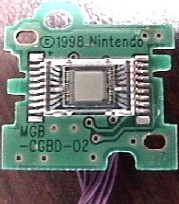
Figure 3. M64282FP CMOS Image Sensor - Lens Removed.
If you decide to remove the image sensor PCB from the eyeball housing, you will see that the image sensor
is mounted on one side of the board (covered by the plastic lens housing), and the
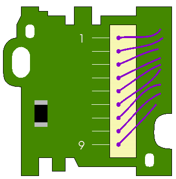
9-way connector is on the other (see Figures 5 and 6).

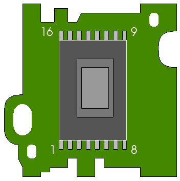
Layout of Image Sensor Circuit Board - Sensor Side (M64282FP pin numbers shown)

Layout of Image Sensor Circuit Board - Back (wire numbers shown)

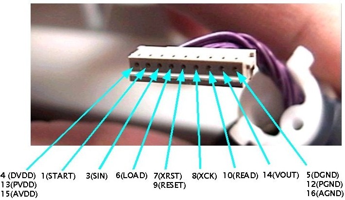
Eyeball Connector Pin-out (M64282FP pin numbers shown)
| Wire |
M64282FP Pin(s) |
Symbol(s) |
Function |
| 1 |
4,13,15 |
DVDD,AVDD1,AVDD2 |
+5V Power Supply |
| 2 |
1 |
START |
Start Input |
| 3 |
3 |
SIN |
Data Input |
| 4 |
6 |
LOAD |
Data Set Input |
| 5 |
7,9 |
Xrst,RESET |
System+Memory Reset Input |
| 6 |
8 |
Xck |
System Clock Input |
| 7 |
10 |
READ |
Read Image Output |
| 8 |
14 |
Vout |
Analog Signal Output |
| 9 |
5,12,16 |
DGND,AGND1,AGND2 |
Ground |
Interface Board:
To interface the cmos captor to a PC we need an Analog/Digital converter to be able to get the value of each pixels. As I am used to the Atmel microcontrollers which are cheap and easy to program in C with AVR GCC, I decided to use an AT90s4433 which has an ADC port, many IO pins and a serial port. The connections between the camera and the microcontroller are direct, you don't need any resistor. To connect the microcontroller to the serial port of a PC you just need a max232 adapter to convert the 5V signal into 12V (see my page about max232)

Interface schematic
Software:
You can download the program for the microcontroller (It compiles with AVR GCC 3.2) and the PC program (Visual Studio) that takes and saves a jpeg picture of the camera :gameboycam2005.07.05.zip
Back
 Back
Back
 Back
Back


